Deutsch
 한국어

Product List
*The Recommended Thrust was calculated at 24V voltage and Rated Current, it has enough safety margin, and it will be 30% higher at 36V and 25% lower at 12V than 24V approximately, pls refer to testing value for actual thrust.
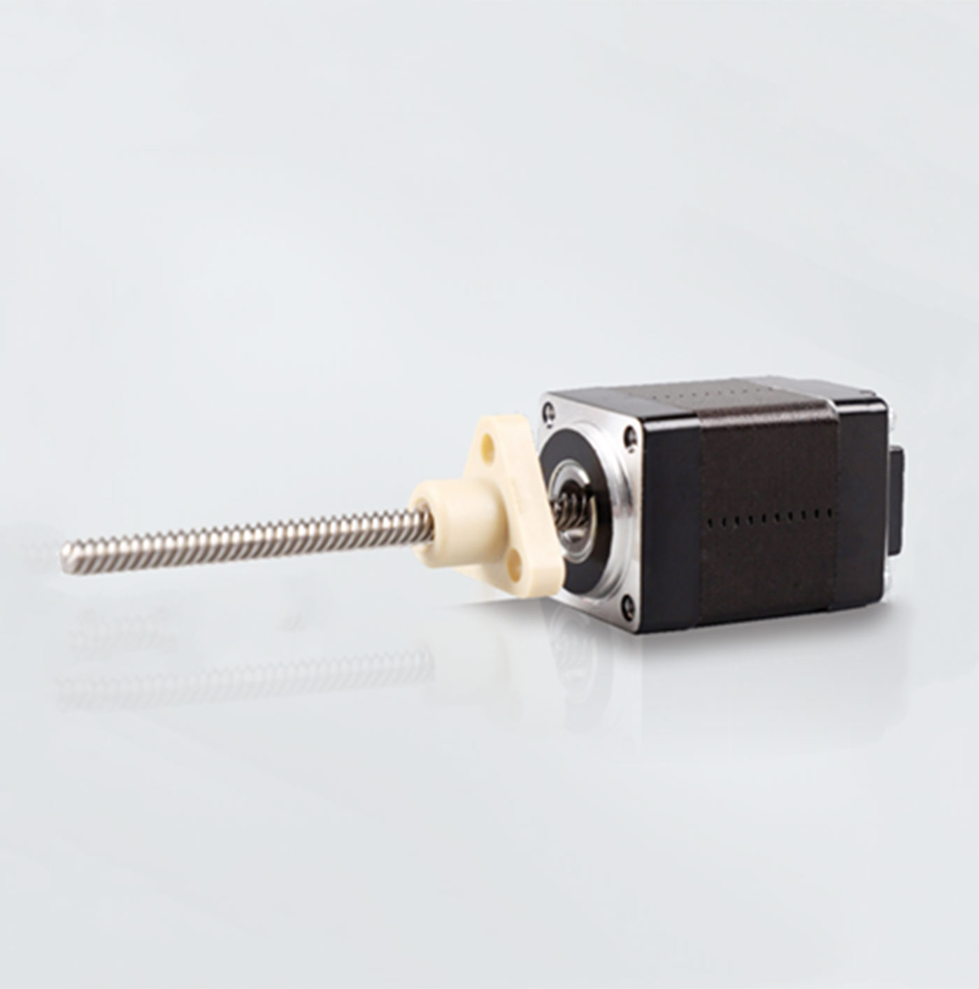
| Item | Phase | Rated Current(A) | Rated Thrust (N @ 300RPM) | Length (mm) | Screw Diameter (mm) | Screw Lead (mm) | Screw Length (mm) | Rotor Inertia (g·cm²) | Technical parameter drawing |
|---|---|---|---|---|---|---|---|---|---|
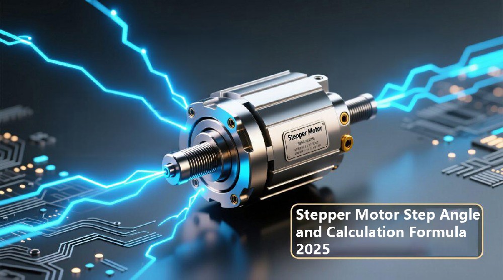
| 08E2004E2-40-G | 2 | 0.4 | 6 | 20.3 | 3.505 | 0.6096 | 40 | 25 |  1.8° Step Angle (200 steps per revolution) • Most common in automation 0.9° Step Angle (400 steps per revolution)• Higher precision Microstepping drivers can further subdivide these angles, improving smoothness at the cost of torque. 5. Why Step Angle Matters in Real Industrial ApplicationsUnderstanding the Stepper Motor Step Angle and Calculation Formula helps engineers: • Determine achievable positioning accuracy For example, if your application requires 0.01 mm linear positioning accuracy, the step angle and screw pitch must be calculated together to ensure the system meets the requirement. 6. Improving Step Resolution: Practical Engineering LimitationsTo achieve a smaller step angle, two strategies exist:
However, rotor pole count is limited by manufacturing constraints. Therefore, high-precision motors often combine optimized rotor design with multi-phase stator systems and microstepping. ConclusionThe Stepper Motor Step Angle and Calculation Formula is essential knowledge for engineers designing motion-control systems. Step angle determines resolution, affects vibration, and directly impacts positioning accuracy. Whether you work with 1.8° motors, 0.9° motors, or custom high-resolution types, understanding step angle formulas helps ensure correct motor selection for automation, robotics, CNC machines, and precision equipment. If you need help choosing the right stepper motor, CYCFLO can provide selection advice and customize motors based on torque, speed, load, and resolution requirements.
Send Inquiry |