
 Deutsch
 한국어

Stepper motors deliver precise, incremental rotary motion in industrial automation systems, converting digital pulses into exact shaft positions without feedback sensors.Design engineers and OEM factories rely on them for open-loop control in CNC machines, robotics, and packaging equipment where position accuracy down to 0.9° steps is critical.
Unlike continuous DC motors, steppers hold position against load torque even when unpowered in some designs, making them ideal for high-holding-torque applications in motion control. CYCFLO offers NEMA-standard hybrid steppers optimized for USA, Germany, Europe, and South Korea markets, balancing cost, torque, and reliability for industrial integrators.
This pillar page covers stepper motor fundamentals, types, performance curves, selection criteria, and OEM sourcing strategies to help procurement managers build robust automation systems.
How Stepper Motors Work
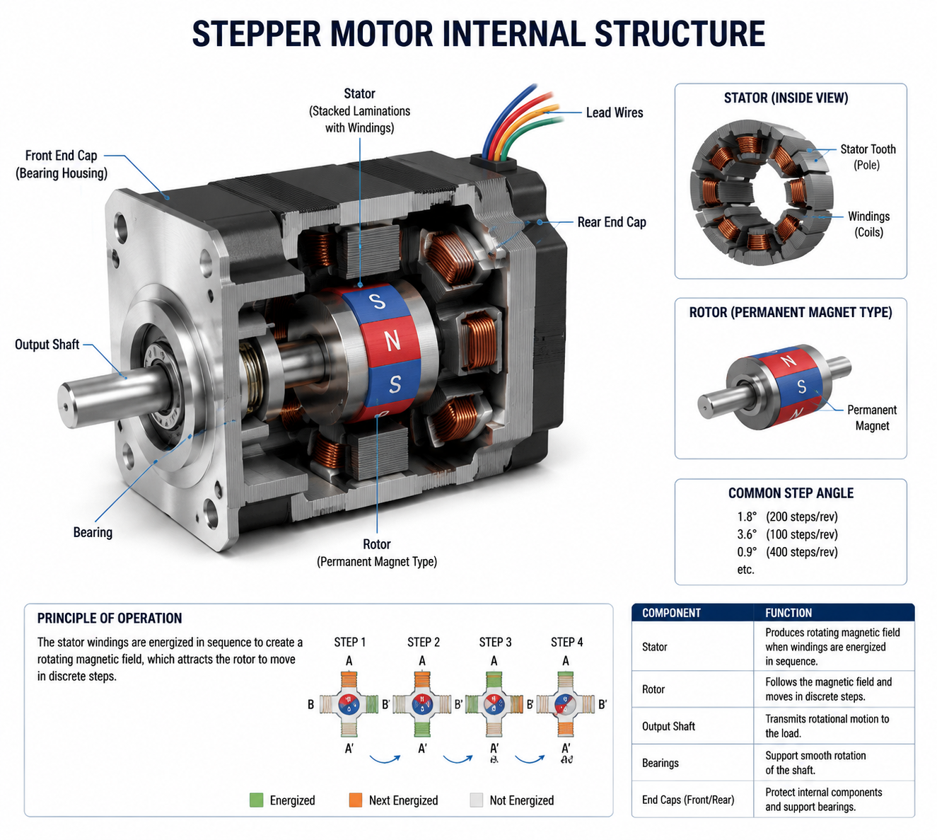
Stepper motors operate by energizing stator coils in sequence to generate rotating magnetic fields that align the rotor in discrete steps. Each electrical pulse advances the shaft by a fixed angle, typically 1.8° for 200 steps per revolution, enabling digital position control without encoders.
The stator features multiple pole pairs with windings, while the rotor—permanent magnet, reluctance, or hybrid—locks into alignment via electromagnetic attraction. Drivers interpret step/direction signals to sequence current through phases, producing smooth or microstepped motion based on control mode.
Stepper Motor Working Principle
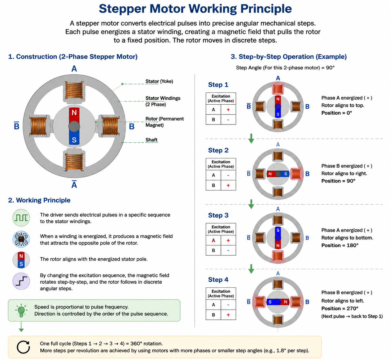
At core, the principle relies on electromagnetic alignment: current in stator coils creates a magnetic field; the rotor aligns its poles or teeth to minimize reluctance. Sequential phase energization—full-step, half-step, or microstep—rotates the field, pulling the rotor stepwise.
In bipolar hybrids, H-bridge drivers reverse current polarity per coil for bidirectional fields, maximizing torque from all windings. Pulse frequency determines speed, while current limits torque; resonance occurs at 50-150 Hz without damping.
For featured snippet: Stepper motors work by converting electrical pulses into precise mechanical steps via sequential stator coil energization, rotating the magnetic field to align the rotor.
Permanent Magnet
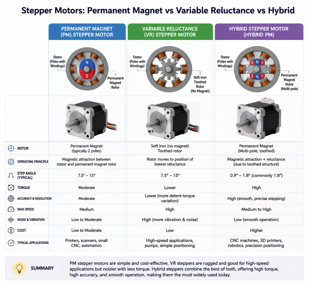
Permanent magnet (PM) steppers use axial magnets in the rotor for detent torque, suiting low-speed, high-holding applications like printer heads. They offer good torque but lower resolution (often 7.5° steps) and speed than hybrids.
Variable Reluctance
Variable reluctance (VR) rotors are soft iron with teeth, aligning to minimize magnetic reluctance paths without magnets. High speed and resolution but no detent torque; used in precision instruments.
Hybrid Stepper Motors
Hybrid designs combine PM rotor with toothed caps and stator for superior torque, resolution (0.9°-1.8°), and speed—dominant in industrial NEMA sizes. CYCFLO hybrids excel in CNC and robotics with minimal step loss under load.
Step Angle and Resolution
Step angle θ = 360° / (steps per revolution), e.g., 1.8° for 200-step motors. Resolution improves via microstepping: 1/16th yields 3200 steps/rev or 0.1125°.
Formula: Steps/rev = phases × rotor teeth / m (microsteps). Engineers calculate load matching: resolution (deg/step) = 360 / steps/rev. For high-precision OEM apps, pair with 0.9° hybrids.
Torque Curves Explained
Torque-speed curves plot available torque vs. pulse frequency: pull-in (start/stop) max at low speed, decreasing hyperbolically; pull-out (sustained) higher but requires ramping. Resonance dip at 100-200 steps/sec demands microstepping or dampers.
Curve regions: constant torque to ~200 RPM, then inductive drop-off. Select drivers boosting voltage for flatter curves in high-speed apps.
Holding Torque vs Running Torque
Holding torque (static) is max at zero speed with full current, resisting loads without motion. Running torque (pull-out) declines with speed due to inductance/back-EMF; pull-in is lower for direct starts.
In industrial use, holding suits clamps; running drives axes—ensure load<80% pull-out at max speed. Hybrids offer 2-15 Nm holding in NEMA 23-42.
NEMA Stepper Motor Sizes
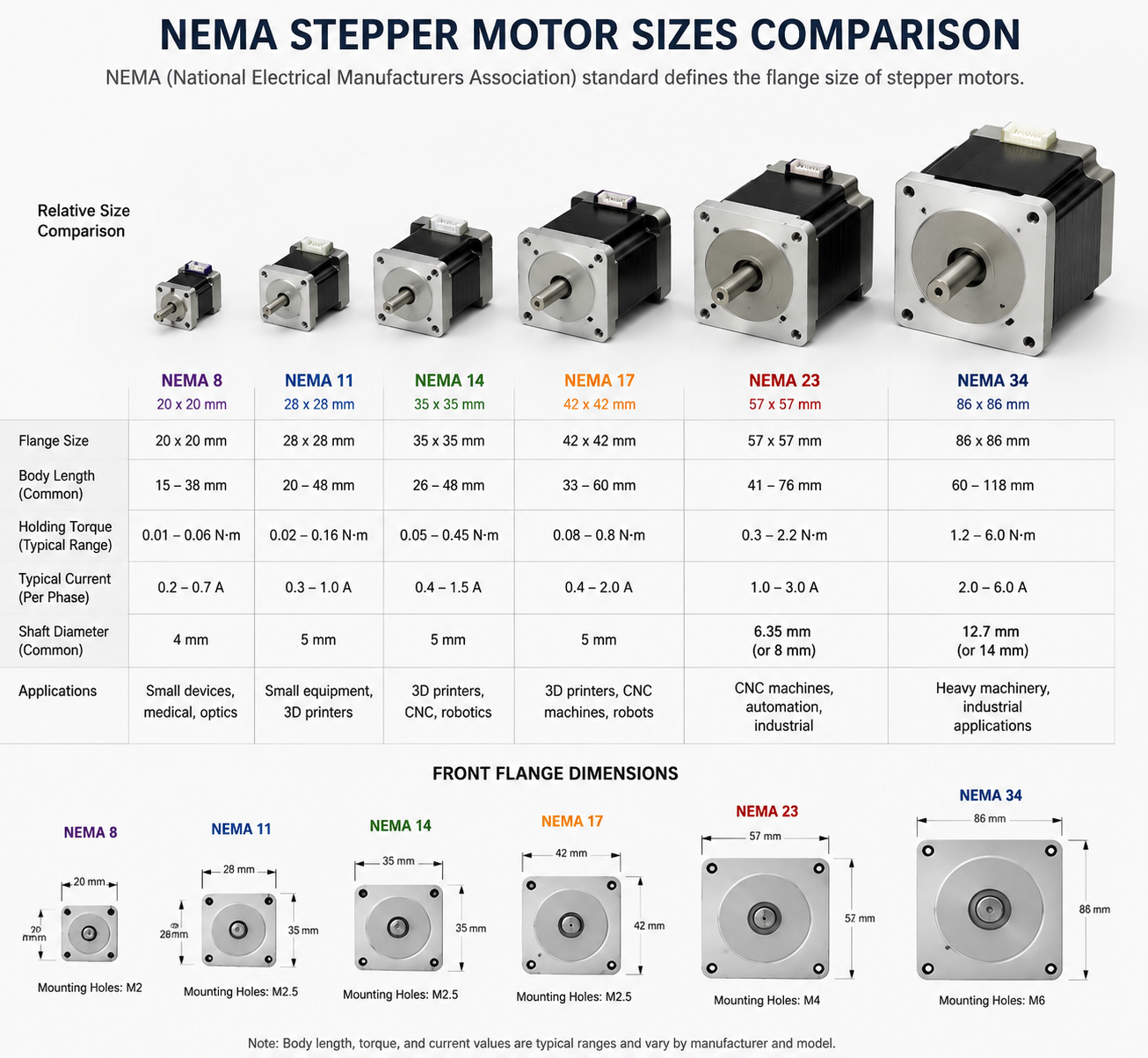
NEMA standards define faceplate dimensions: NEMA 17 (42mm) for light CNC, NEMA 23 (57mm) for medium routers. Larger NEMA 34/42 handle heavy industrial loads.
| NEMA Size | Frame (mm) | Typical Holding Torque (Nm) | Applications |
|---|---|---|---|
| NEMA 17 | 42x42 | 0.2-0.88 | 3D printers, small robots |
| NEMA 23 | 57x57 | 0.59-3.4 | CNC spindles, AGVs |
| NEMA 34 | 86x86 | 2.8-15 | Heavy automation |
Learn NEMA 17 vs NEMA 23 differences for your build.
Closed Loop Stepper Motors
Closed-loop adds encoders for feedback, correcting lost steps and boosting high-speed torque vs. open-loop. Ideal for dynamic loads in robotics; CYCFLO closed-loop systems maintain 100% accuracy.
Advantages: higher speed/torque, efficiency; drawbacks: cost, complexity. See our closed loop stepper motors page.
Stepper Motor Drivers
Drivers handle current chopping, microstepping (1/256), and interfaces (step/dir, PWM). Bipolar H-bridges for hybrids; select by motor current (1-10A).
Chopper types regulate torque; advanced ICs like MP6501A prevent overheating. Explore stepper motor drivers.
Stepper Motor Wiring Basics
Bipolar: 4 wires (two coils A+/A-, B+/B-); unipolar: 5-6 with center taps. Sequence: 1-2-3-4 for full-step CW.
Miswiring causes vibration; use A4964 diagrams for verification. Details in stepper motor wiring guide.
Microstepping Technology
Microstepping sinusoidally varies phase currents for 1/32+ resolution, reducing resonance/vibration. Tradeoff: lower torque per step, potential skipping at extremes.
Essential for smooth CNC; drivers like TMC2209 enable 256 microsteps.
Stepper Motor Applications
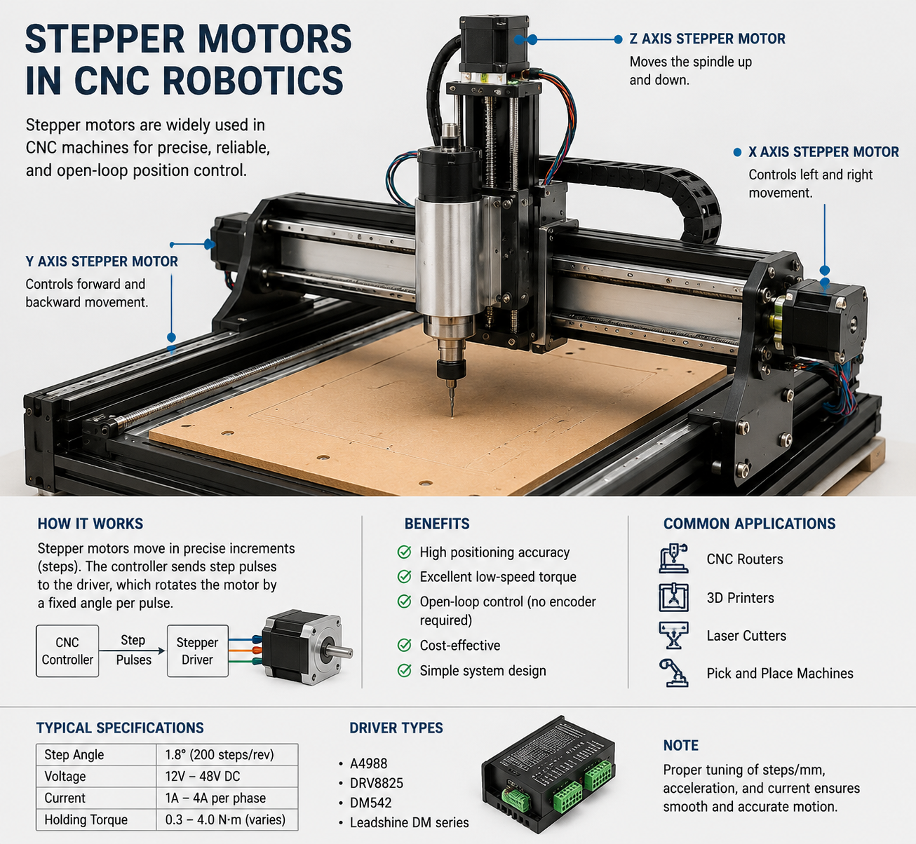
CNC
XY/Z axes positioning; NEMA 23 hybrids for rigidity.
Robotics
Joint actuation; precise steps for end-effectors.
Medical Equipment
Pump dosing, scanner beds; hygiene-rated hybrids.
Packaging Machinery
Fill/seal indexing; high cycle rates.
AGV
Wheel drive/navigation; closed-loop for loads.
Stepper Motor vs Servo Motor
| Aspect | Stepper | Servo |
|---|---|---|
| Control | Open-loop pulses | Closed-loop feedback |
| Torque/Speed | High low-speed hold | High dynamic speed |
| Cost | Lower | Higher |
| Precision | Step-based | Continuous ±0.01° |
Steppers for cost-sensitive positioning; servos for velocity. Full vs servo comparison.
Stepper Motor Selection Guide
1. Calculate load torque + inertia + accel.
2. Match NEMA size/holding >1.5x load.
3. Verify speed-torque curve.
4. Driver current/voltage.
5. Microsteps for res. CYCFLO consult for custom. See torque calculator.
Common Stepper Motor Problems
Lost steps: overload > pull-out.
Overheating: high current, poor cooling.
Resonance: 100Hz vibration; microstep/damp.
Troubleshoot: check wiring, ramp rates. Guide: overheating fixes.
OEM & Industrial Sourcing Guide
Evaluate factories on ISO certs, MOQ, lead times, customization (shafts/gears). CYCFLO: 20+ years, global shipping, engineering support for USA/EU/Korea.
FAQs
How do stepper motors work?
By sequential coil energization creating rotating fields for step alignment.
What is a closed loop stepper motor?
Open-loop with encoder feedback for error correction.
Stepper vs servo motor?
Steppers: simple, low-speed torque; servos: high-speed precision.
What is holding torque?
Max static torque at rest.
NEMA 17 vs 23?
17: light duty; 23: higher torque.
How to calculate stepper torque?
Load + friction + accel; tools here.
Why do steppers overheat?
Constant current draw; use choppers, heatsinks.
What is microstepping?
Fractional steps via current modulation.
Best stepper for CNC?
NEMA 23 hybrid, 2-4A driver.
Stepper motor wiring colors?
Bipolar: A+ green, A- red, B+ blue, B- black typical.
Conclusion
Stepper motors anchor industrial motion control with unmatched position certainty and torque. Partner with CYCFLO for tailored solutions driving your automation forward. CYCFLO stepper motor technical guide covers the torque-speed curves and driver interaction in more depth.
| Microstep Setting | Steps/Rev (1.8° motor) | Theoretical Resolution | Practical Positioning Accuracy | Primary Benefit |
|---|---|---|---|---|
| Full step | 200 | 1.8° | ±0.09° (typical) | Maximum torque, simplest driver |
| Half step | 400 | 0.9° | ±0.05° | Reduced resonance, moderate smoothness |
| 1/8 step | 1600 | 0.225° | ±0.05° (load dependent) | Smooth motion, noise reduction |
| 1/16 step | 3200 | 0.1125° | ±0.05° (no improvement) | Smoother velocity profile |
| 1/32 step or finer | 6400+ | <0.06° | No measurable improvement | Noise reduction only |
The ±0.05° figure that appears repeatedly in that table reflects the inherent mechanical accuracy of the motor itself — the tolerance on rotor tooth geometry, stator pole alignment, and bearing runout. This is a manufacturing specification, not a function of step resolution. No amount of microstepping can improve on it. Engineers who need positioning accuracy beyond what the motor's mechanical tolerance allows need closed-loop feedback, not a higher microstep ratio.
System-Level Resolution: Motor to Load
Step angle at the motor shaft is only the starting point. What matters in the application is the resolution at the load — the linear displacement per step for a leadscrew axis, or the angular increment per step for a rotary table.
A 1.8° motor driving a 5mm-pitch leadscrew directly produces 5mm / 200 steps = 0.025mm per full step. With 1/8 microstepping, that becomes 0.003125mm per microstep — which sounds impressive until you account for leadscrew backlash, which in a typical rolled ballscrew is 0.01–0.05mm. The microstep resolution is smaller than the mechanical backlash, making it irrelevant to actual positioning accuracy.
This is a common design error in CNC and automation systems: specifying high microstepping ratios to achieve a resolution number on paper while the mechanical transmission limits real accuracy to a much coarser value. The correct approach is to match the step resolution to the mechanical accuracy of the transmission, then use microstepping only to the extent needed for smooth motion.
Application Selection Logic
For CNC router and mill axis control, the 1.8° motor with 1/8 or 1/16 microstepping covers most requirements. The mechanical transmission — ballscrew pitch, belt reduction ratio — typically limits positioning accuracy to 0.01–0.05mm, which is well within what a standard 200-step motor can resolve. The priority is torque consistency across the operating speed range, which favors the 1.8° design.
In 3D printing, the motion system runs at relatively low speeds with light loads. Torque ripple translates into surface artifacts — the banding visible on printed walls at certain layer heights corresponds to the step frequency interacting with the frame's resonance. Here, 0.9° motors or 1/16 microstepping on 1.8° motors both reduce this effect, and the choice often comes down to driver availability and cost.
Medical peristaltic and syringe pump applications are where 0.9° motors earn their place. Flow rate accuracy depends on velocity uniformity, and the smoother torque profile of the 0.9° motor at low RPM reduces pulsation. These systems also tend to run at fixed, low speeds where the 0.9° motor's reduced high-speed torque is not a constraint.
Packaging indexing systems present a different set of priorities. The motion profile is typically a fast index followed by a dwell — high acceleration, moderate speed, hard stop. Torque at speed matters more than low-speed smoothness. The 1.8° motor's better high-speed torque retention and stronger detent at rest (which helps hold position during the dwell without continuous current) makes it the standard choice here.
| Application | Recommended Step Angle | Microstepping | Primary Constraint |
|---|---|---|---|
| CNC axis (ballscrew) | 1.8° | 1/8 to 1/16 | Torque at speed, transmission accuracy |
| 3D printer (Cartesian/CoreXY) | 0.9° or 1.8° | 1/16 to 1/32 | Surface finish, resonance artifacts |
| Medical pump (peristaltic) | 0.9° | 1/8 | Velocity uniformity, torque ripple |
| Packaging indexer | 1.8° | Full or half step | Acceleration torque, dwell holding |
| Optical positioning stage | 0.9° | 1/8 to 1/16 | Low-speed smoothness, repeatability |
Practical Notes on Driver and Motor Matching
The step angle selection doesn't exist in isolation from the driver. A 0.9° motor running at 1/16 microstepping on a driver with a 24V supply will have a very different torque-speed curve than the same motor on a 48V supply. The higher voltage allows faster current rise in the windings, which partially compensates for the inductance penalty of the 100-tooth rotor at higher step rates. If the application requires a 0.9° motor to run at moderate speeds, the supply voltage needs to be sized accordingly — typically 20–25× the motor's rated voltage is a reasonable starting point for the driver supply.
Current setting also interacts with step angle behavior. Running a motor at reduced current to limit heat dissipation reduces holding torque at each microstep position, which increases the susceptibility to position error under load. In systems where thermal management pushes toward lower current settings, the 1.8° motor's stronger full-step detent provides more margin than the 0.9° motor operating at the same reduced current.
The decision between 1.8° and 0.9°, and the choice of microstepping ratio, should follow from the actual motion requirements: the required resolution at the load, the operating speed range, the load torque and inertia, and the acceptable velocity ripple. Working backward from those constraints to the motor and driver specification produces a more reliable system than working forward from a resolution target on the motor datasheet.
Frequently Asked Questions
Does a smaller step angle always mean better positioning accuracy?
Not in practice. Step angle determines the resolution the motor can theoretically achieve at the shaft. What limits actual positioning accuracy is the mechanical system — leadscrew backlash, belt stretch, bearing play, and the motor's own tooth geometry tolerance. A 0.9° motor in a drivetrain with 0.05mm of backlash does not position more accurately than a 1.8° motor in the same drivetrain. If shaft-level accuracy is the requirement, the motor's mechanical tolerance spec (typically ±0.09° for a 1.8° motor, non-cumulative) is the relevant number, not the step angle.
Can I use high microstepping to replace a closed-loop system?
No. Microstepping controls the current vector, not the rotor position. If the load torque at a microstep position exceeds the available holding torque at that point — which is reduced compared to a full-step position — the rotor will slip without the controller knowing. Open-loop stepper systems have no position feedback by definition. High microstepping ratios reduce velocity ripple and noise, but they do not add position verification. Applications that cannot tolerate missed steps or position drift under variable load need an encoder and closed-loop control, regardless of the microstepping ratio.
Why does my stepper motor vibrate badly at certain speeds but run smoothly at others?
This is resonance. The motor-load system has a natural frequency determined by rotor inertia, load inertia, and magnetic spring stiffness. When the step rate matches or approaches this frequency, the rotor oscillates rather than stepping cleanly. The fix depends on where the resonance falls relative to the required operating speed. Options include switching to a higher microstepping ratio to pass through the resonance band faster, adding a mechanical damper, adjusting the acceleration ramp to avoid dwelling at the resonant speed, or — if the operating speed is fixed — selecting a motor with a different rotor inertia that shifts the resonance out of the problem range.
What is the practical difference between 1/16 and 1/32 microstepping?
At 1/16 microstepping on a 1.8° motor, the theoretical step size is 0.1125°. At 1/32, it is 0.05625°. In mechanical terms, neither of these is achievable as a repeatable positioning increment under real load conditions — the motor's magnetic nonlinearity and manufacturing tolerances dominate at this scale. The audible difference between 1/16 and 1/32 is also minimal in most systems. Specifying 1/32 or finer is rarely justified by engineering requirements; it typically reflects a misunderstanding of what microstepping delivers mechanically.
Is a 0.9° motor a drop-in replacement for a 1.8° motor?
Electrically, many 0.9° motors share the same frame size and connector pinout as their 1.8° counterparts, so physical installation is usually straightforward. The driver configuration needs to change — the step pulse count per revolution doubles, so motion profiles need to be recalculated. More importantly, the torque-speed curve is different. If the existing system was sized with margin on a 1.8° motor, the 0.9° motor may underperform at the upper end of the speed range due to its higher inductance. Verify the torque requirement at maximum operating speed against the 0.9° motor's curve before substituting.
How does load inertia affect step angle selection?
High load inertia relative to rotor inertia makes the motor harder to accelerate and more prone to overshoot at each step. In full-step mode, this overshoot can cause the rotor to oscillate around the target position before settling — a behavior that worsens near resonance. Microstepping reduces the per-step angular impulse, which helps damp this oscillation. As a general guideline, inertia ratios above 10:1 (load to rotor) warrant careful evaluation of the step rate and microstepping setting, and may indicate that a gearhead or a larger motor frame is a better solution than increasing the microstepping ratio.
At what point should I switch from a stepper to a servo for a precision axis?
The crossover point depends on three factors: speed, load variability, and accuracy requirement. Steppers work well at low-to-medium speeds with predictable loads and positioning tolerances above roughly 0.01mm at the load. When the application requires high speed with sustained torque, variable loads that could cause missed steps, or sub-0.01mm repeatability with verification, a servo with encoder feedback is the appropriate choice. The cost difference has narrowed considerably with compact closed-loop stepper systems, which add an encoder and position correction loop to a standard stepper motor — a practical middle ground for applications that need position verification without full servo complexity.